23. The Speed of Light
23.1. Background
The speed of light \(c\) is one of the most important constants in nature. In vacuum \(c\) is independent of the reference frame. Its magnitude determines when classical Newtonian mechanics, which is a limiting case for small velocities, needs to be replaced by the more general relativistic mechanics. The fact that Newtonian mechanics is so successful describing ‘everyday’ mechanical phenomena is an indication that the speed of light is very large and therefore not easy to measure. The precision with which the speed of light is determined is continually being improved since in combination with ultra high precision time measurements it forms our length standard.
In this experiment you will use a setup based on L.Foucault’s design with which measured \(c\) which deviated on by about 0.6% from the currently accepted value. The principle setup for the measurement is shown in Fig. 23.1.
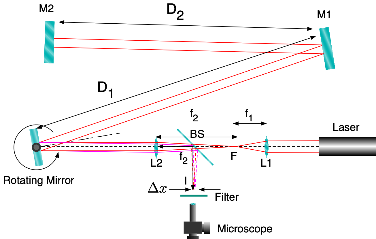
Fig. 23.1 Schematic of the setup to measure the speed of light.
The light from a laser is focused at point F by lens L1. Point F is also the focal point of lens L2. From point F the laser light passes through a beam splitter (BS) and emerges from lens L2 as parallel light (L2 forms an image of F at infinity). After L2 the light is reflected from the surface of a rotating mirror towards a flat, fixed mirror M1 and from there to a second flat mirror M2. From M2 the light is reflected back and in the ideal case travels the same path in the opposite direction, passing through lens L1 which produces an image at F. In order to be able to observe the reflected light the beam splitter reflects a fraction of the returning light at \(90^\circ\) where the image at I can be observed with a measuring microscope. This image is only formed where the rotating mirror is at just the correct rotation angle \(\phi\). Fig. 23.2 shows the laser beams during the alignment of the instrument. The beams are made visible by a small amount of smoke in the air and a dark filter is placed in front of the microscope for eye protection.
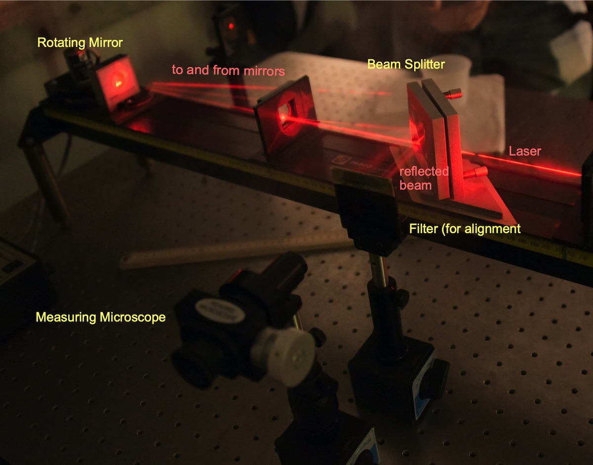
Fig. 23.2 Laser beams during alignment.
Since the propagation speed of the light is finite by the time the reflected light (from mirrors M2 and M1) hits the rotating mirror, the mirror has continued its rotation and has a slightly different orientation compared to when the light was propagating towards M1 and M2. This will lead to a shift of the image at I which can bea measured with the microscope.
In order to find the relation between the measured shift \(\Delta x\) and \(c\) one needs first to study the angles involved at the rotating mirror (Fig. 23.3)
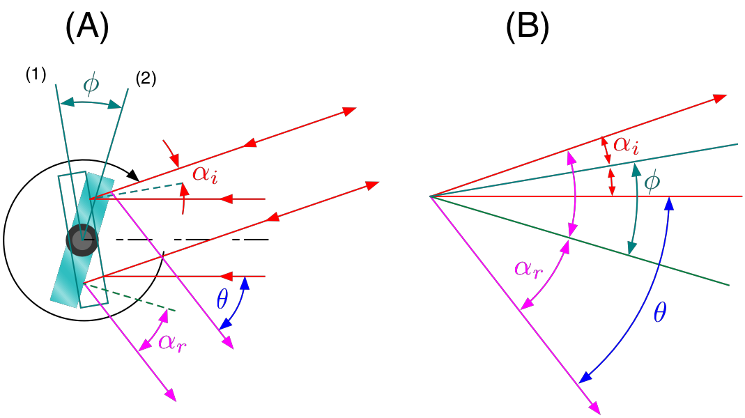
Fig. 23.3 Reflection of the primary and the reflected beams at the rotating mirror. (A) Rotating mirror at positing when primary beam is reflected (1) and its orientation when the reflected beam is being reflected (2). (B) Angular relations.
Panel (A) shows the orientation of the mirror when light from the laser hits its surface for the first time with and angle of incidence \(\alpha_i\) (red arrows). By the time the light returns from being reflected by the mirrors M1 and M2 the rotating mirror has rotated through an angle \(\phi\) and the light is reflected from its surface with a reflection angle \(\alpha_r\). If the speed of light were infinite one would have \(\alpha_i = \alpha_r\), instead the reflected beam from the rotating mirror makes an angle \(\theta\) with respect to the incident beam. As is shown in Fig. 23.4
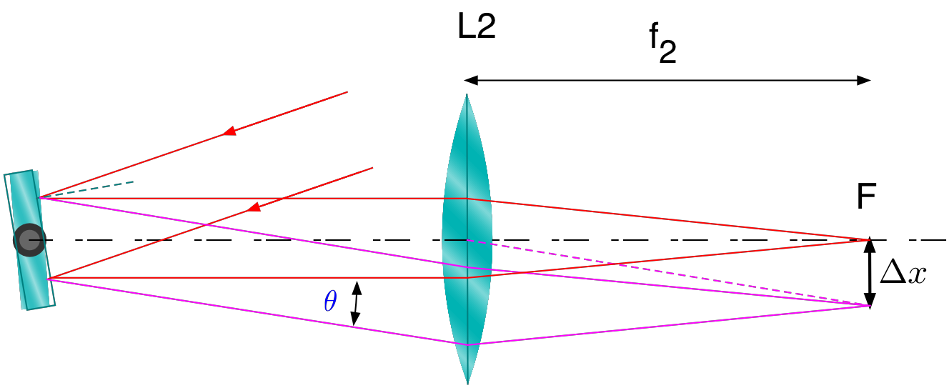
Fig. 23.4 Formation of the image of the reflected light. The shift \(\Delta x\) is due to the angle \(\theta\) of the reflected light (magenta beams)
The reflected parallel light is incident on L2 with and angle \(\theta\) and is focused in the focal of L2 at a position \(\Delta x\) from the optical axis. \(\Delta x\) can be calculated as follows:
From Fig. 23.3 (B) one obtains:
For the rotation angle:
where \(\omega\) is the angular velocity of the rotating mirror. Combining (23.3), (23.2) and (23.1) one obtains the relation:
From this relation one can determine the speed of light \(c\).
23.2. Experimental Equipment
The main parts are shown in Fig. 23.5
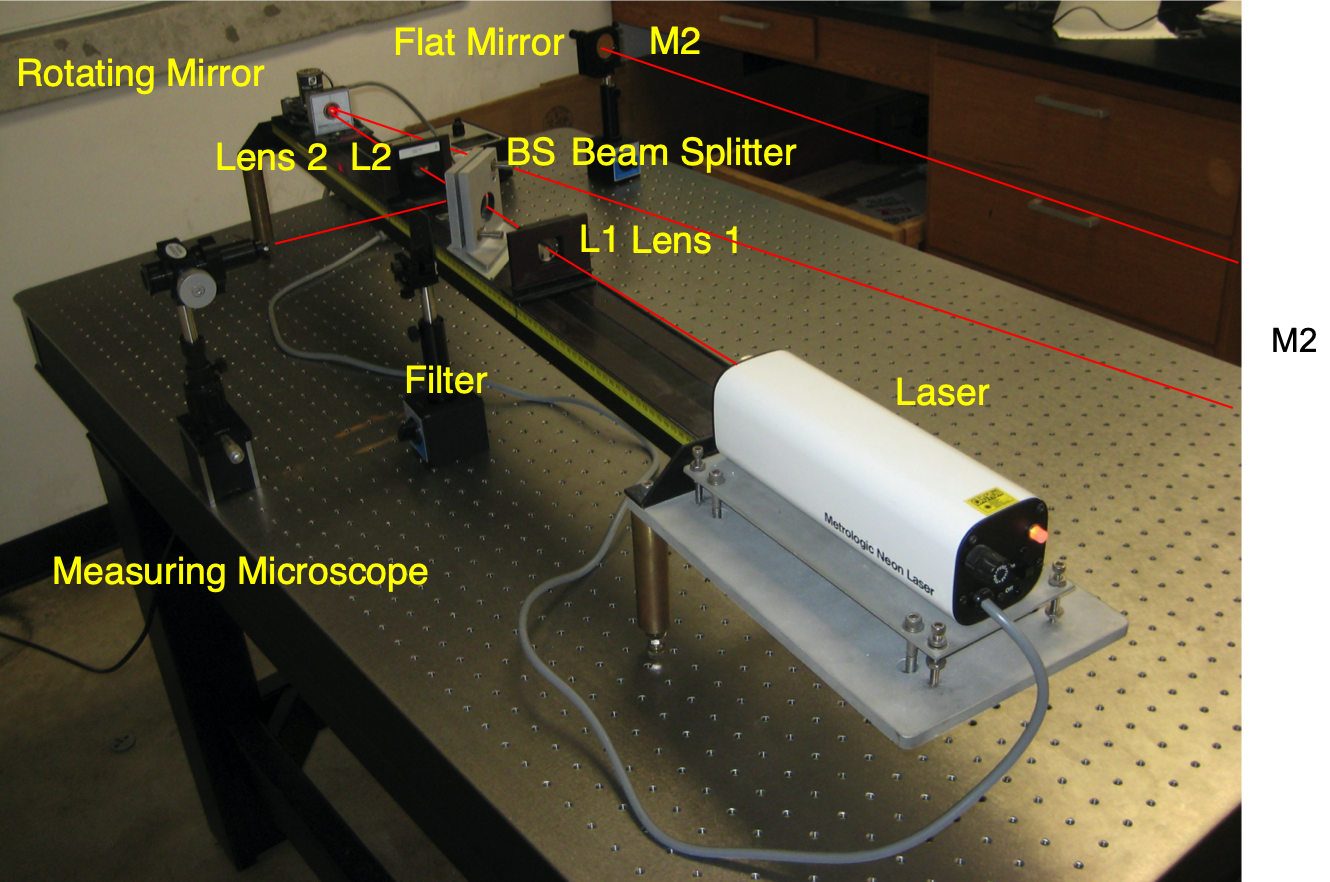
Fig. 23.5 Overview of the apparatus to measure the speed of light
The rotating mirror assembly, its controls and are shown in Fig. 23.6
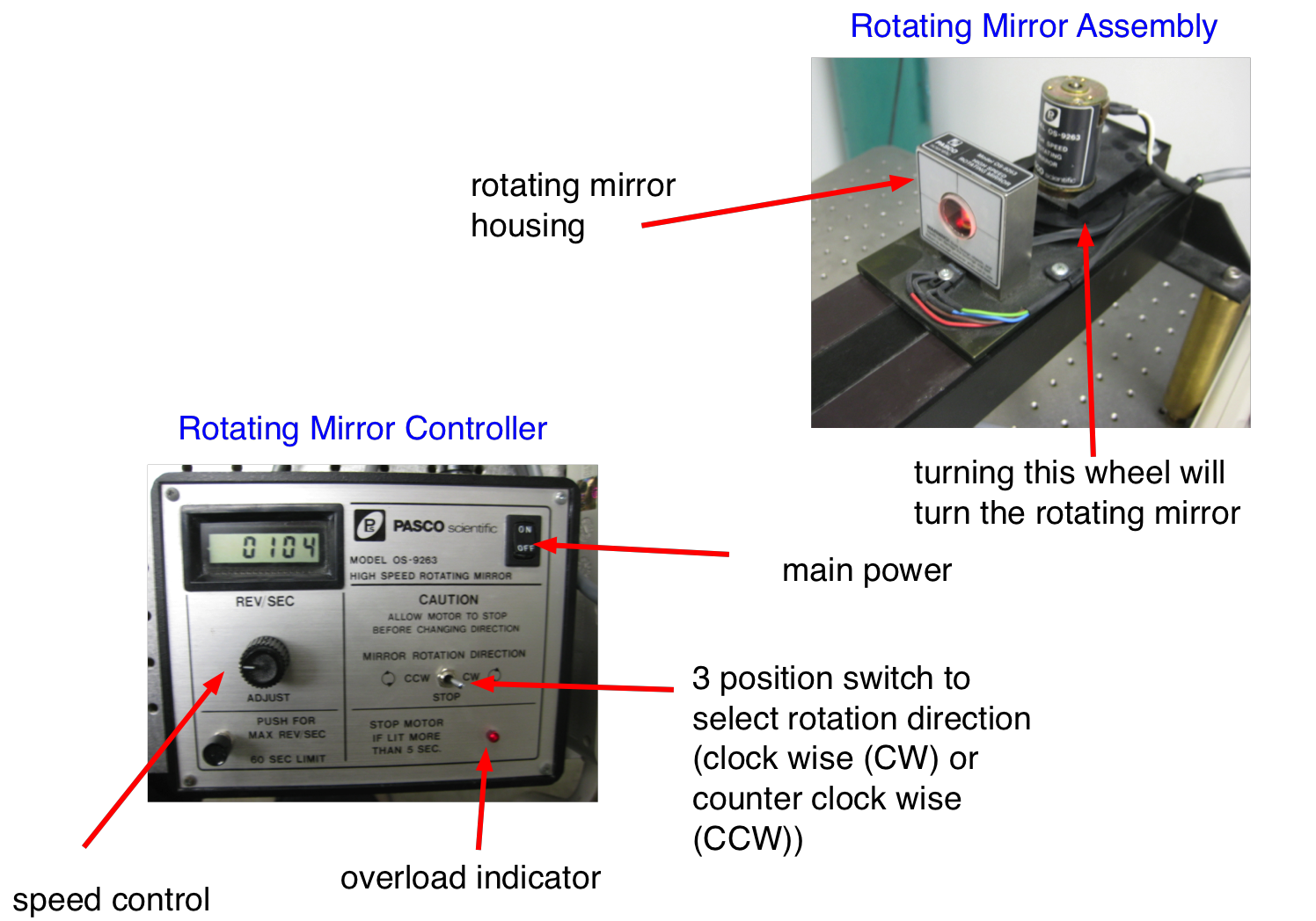
Fig. 23.6 Rotating mirror assembly and the control unit for the rotating mirror.
23.3. Pre-Lab Preparation
Assume the image position you observed is 4.105mm, when the rotating mirror is set to rotate at 1000Hz in CW direction; and 4.610mm at 1000Hz in CCW direction; Compute the speed of light; Assume the focal length of the second lense is 25.60cm, and the distances between the rotating mirror and the reflecting mirrors are D1=D2=8.000m. (Do not try to compute a value of \(c\) for each data point (this is not possible), use the two data points together to obtain a value for \(c\))
Prepare the data files to enter the experimental data.
What other distances do you need to measure and estimate their uncertainties?
23.4. Experimental Procedure
When you are working with optical equipment NEVER touch the optical surface with your fingers! If you have to tighten set screws use only two fingers and do not apply a lot of force or you might crack a lens or a mirror. The various optical parts are labeled. If you are unsure ask your instructor or learning assistant for help.
Check the alignment of the instrument, When the mirror is not rotating you should use the dark filter before looking at the image.
23.4.1. Carry out the measurements
Select the rotation direction
Set the rotation speed to low and make sure you can see the flickering image. Position the cross hair to the right of left of the image by turning the micrometer drum at the side. Each unit is 1/100 of a mm. Record the number
Increase the rotation frequency in steps of 100Hz - 200Hz. At each frequency measure the position of the image.
Repeat until you reach 1000Hz.
Stop the rotating mirror and repeat the measurements for the other rotation direction.
23.5. Analysis
From the position measurements subtract the position for zero (or very slow) rotation. For the analysis of image data, use the Image Analyzer
Plot the measured \(\Delta x\) as a function of \(\omega\). Select different signs for CW and CCW rotation.
You should obtain a straight line according to (23.4).
Fit a line and from the slope determine \(c\) and its error.
Using (23.4) you can also determine \(c\) from each measurement taking into account all errors of the measured quantities. From all your data points determine the average value of \(c\) and its error and compare to the previous result.