16. Michelson Interferometer
16.1. Background
Interferometers generally are used to measure very small displacements by using the wave property of light (or other radiation e.g. low energy neutrons). They measure changes of the interference pattern when waves with different phases overlap. While in a spectrometer (see the hydrogen spectrum experiment) the displacements between the sources are known (e.g. in a grating) one can determine wave properties e.g. the wave length. If, on the other hand, the wavelength is known one can use this principle to measure displacements of the order of the wavelength of the light used.
Michelson Interferometer is probably best known in connection with the Michelson-Morley experiment, in which an unsuccessful attempt was made to demonstrate the existence of an “ether”, a hypothetical medium supposed to be necessary for the propagation of electromagnetic waves.
The purpose of this experiment is to give you some practice in assembling, aligning and using a Michelson interferometer to measure the index of refraction of air.
The principle of the Michelson interferometer is shown in Fig. 16.1. Light from a laser is incident on a beam splitter (BS) which consists of a glass plate with a partially reflective surface. About 50% of the light is reflected from the surface and 50% is transmitted. The reflected light (beam 1) hits mirror M1 and is reflected back towards the beam splitter. The transmitted light (beam 2) as well is reflected back towards the beam splitter by mirror M2. 50% of the intensity of each reflected beam is transmitted/reflected towards the screen for observation. There the two beams overlap and constructive and destructive interference occurs depending on the relative phase shift between the two plane waves.
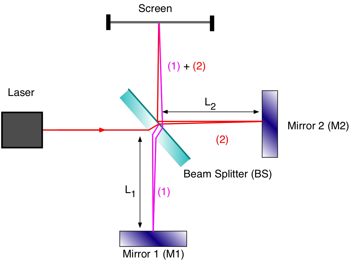
Fig. 16.1 Schematic of the Michelson interferometer.
Each beam experiences a phase shift of \(\phi = 180^\circ\) when they are reflected at the mirror surfaces M1 and M2 and an additional phase shift \(\phi'\) due to the propagation through the glass of the beam splitter and the partial reflection at the semi-transparent surface. The total phase shift between the two beams therefore is given by:
Here \(k\) is the wave number and \(\lambda\) the wave length of the light. You will observe constructive interference when the \(\Phi = m 2\pi\) with \(m = 0,1,2,...\). If e.g. \(L_1\) changes continuously and \(L_2\) is kept fixed one observes changes of constructive and destructive interference. The number \(\Delta m\) of changes is given by:
Therefore this instruments allows you to observe distance changes of the order of the wavelength of light.
If light travels in a medium its speed is smaller than in vacuum. The ratio between the speed of light in vacuum (\(c_{vac}\)) and the speed of light in a medium (\(c_{med}\)) is give by the index of refraction \(n = c_{vac}/c_{med}\). As a consequence if light travels a distance \(x\) in a medium it experiences a phase shift \(k_{med} x\) where \(k_{med} = 2\pi/\lambda_{med}\) and \(\lambda_{med} = \lambda/n\), the wavelength of light in a medium is shorter that in vacuum. This property is later used to determine the index of refraction of air.
16.2. Experimental Equipment
The main parts are shown in Fig. 16.2
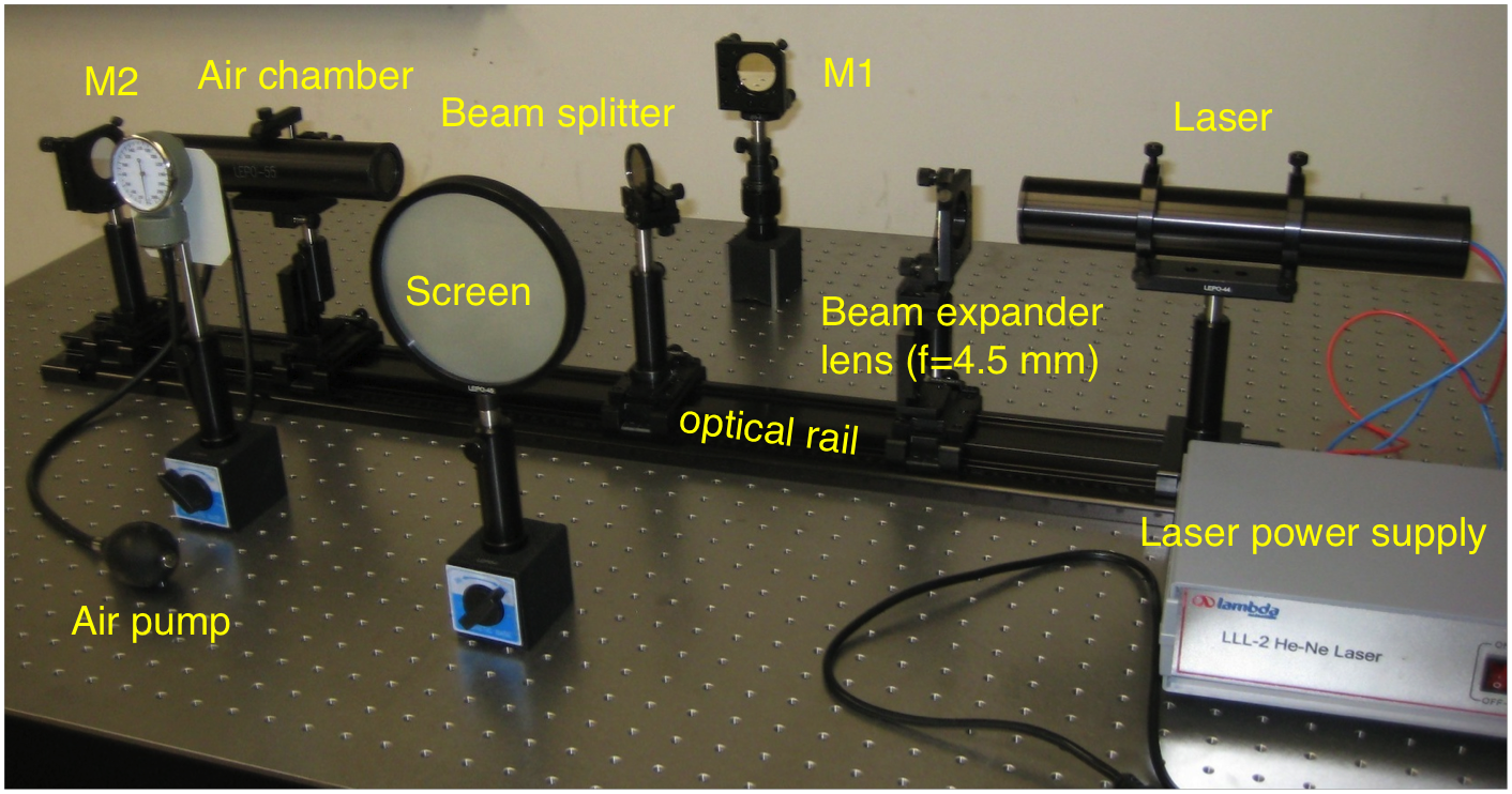
Fig. 16.2 Assembled Michelson interferometer.
16.3. Experimental Procedure
When you are working with optical equipment NEVER touch the optical surface with your fingers! If you have to tighten set screws use only two fingers and do not apply a lot of force or you might crack a lens or a mirror. The various optical parts are labeled. If you are unsure ask your instructor or learning assistant for help.
16.3.1. Assembling the Interferometer
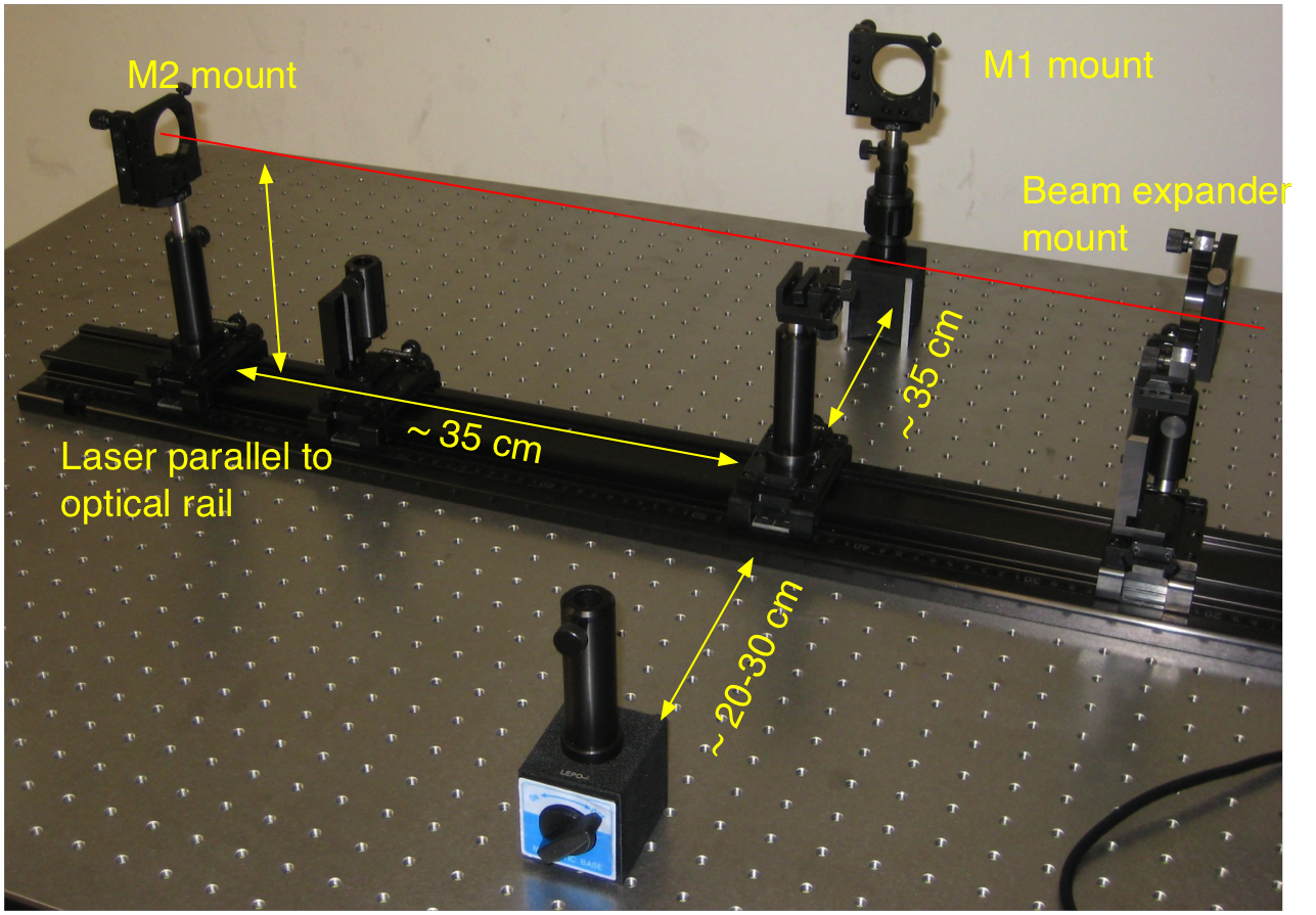
Fig. 16.3 Setup of the lens and mirror supports.
Arrange the support parts as shown in Fig. 16.3. Note the various part are labeled.
Set the height of the laser to about 16.5 cm above the optical rail and make sure all components are at the aligned at the same height.
Turn the laser on. Adjust the output of the He-Ne laser parallel along the optical rail (beam expander lens should not be inserted at this moment) by carefully adjusting the set screws of the laser mount,
Put in the beam splitter (BS) at an angle of \(45^\circ\) with respect to the beam axis, and adjust its tilt to make the two beams (transmission and reflection) parallel to table.
Adjust the tilt of mirrors M1 and M2 to make the reflected beams coincide with their incident paths, and the two beam spots on the screen S overlap together. Also make sure that the beam spots on the beam splitter overlap as close as possible.
Insert the beam expander lens, then finely adjust beam splitter, M1 and M2, till concentric interference rings can be observed on the screen S
Carefully press on the optical table and observe how the fringes change. Interpret this result. By how much does the difference \(|L_1 - L_2|\) change ?
Insert the air chamber between beam splitter and M2 and adjust it parallel to optical path. Mount the manometer as shown. Make sure you still see the interference fringes.
At this point you might find that the system is very sensitive to vibrations. Ask the instructor to let the optical table float. Once the table floats on air your instrument should be much less sensitive to vibrations and be ready for measurements. DO NOT LEAN ON THE TABLE WHEN IT IS FLOATING!
Pump air into the air chamber till the maximum allowed pressure (40 kPa or 300 mm Hg) is reached and write it as \(\Delta P\)
Slowly release the air valve and count the number of interference rings changing (appearing or disappearing) in the center till air pressure falls back to zero.
Repeat the previous two steps several times to obtain an average value and an uncertainty.
From these data you can now determine the index of refraction of air.
16.4. Analysis
The index of refraction of air is very close to one. It is a good approximation to assume that the deviation from one is proportional to the density of air:
Air is treated as an ideal gas with its equation of state:
Inserting into (16.3) gives
Assuming that the temperature is constant \(T_0 = T\) and using \(\Delta n = n - n_0\) and \(\Delta P = P - P_0\) one obtains:
When the air pressure in the air chamber changes the index of refraction changes as given by (16.6). When beam 2 travels through the air in the chamber which has a length \(l\), its phase shift is \(k_{med} l = k_{vac} n l\). The quantity \(n l\) is also called the optical path length and gives the effective distance a wave would have to travel in vacuum to experience the same phase shift as in a material of thickness \(l\) and index of refraction \(n\). With the air chamber (16.2) becomes:
There for by counting the number of fringes (maxima or minima) you get \(\Delta m\). Combining (16.7) with (16.6) you can solve for \(n_0\) the index of refraction of air. Determine its value and its uncertainty.